Unity Shader Graph Advanced Techniques 2026
Go past your first Shader Graph material and build a dissolve that eats an object away with a glowing edge, then drive it from a script.
In the beginner Shader Graph guide, you built a lit material with a color, varied smoothness, and a fresnel rim. That taught you the core loop: add a property, process it with nodes, send it to an output.
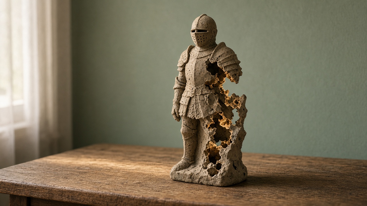
This guide uses that loop for something new. You will build a dissolve. An object breaks apart in an irregular pattern, with a bright edge where the surface is disappearing. It is a classic look for defeated enemies, teleporting characters, and props that fade out of a level.
You will finish with a slider that dissolves any object, plus a few lines of code to trigger it in play.
This guide assumes the Universal Render Pipeline and a Lit Shader Graph. Node names and Graph Inspector options shift between versions. If something below does not match your editor, check the Shader Graph and URP documentation for your exact version.
How a dissolve works
The idea is simple. Every pixel on the surface gets a random-looking value from a noise pattern. You pick a threshold. Any pixel whose noise value falls below the threshold gets thrown away, so you see through the object there.
Raise the threshold, and more pixels get thrown away. The object vanishes in patches.
Shader Graph has a built-in way to throw pixels away: alpha clipping. Unity’s documentation describes the Alpha Clip Threshold output as discarding fragments whose alpha falls below that value. So you feed noise into Alpha, feed your threshold into Alpha Clip Threshold, and the graph does the discarding for you.
The glowing edge comes from a second test: find pixels just above the threshold and make them emit light.
Create the graph and turn on clipping
- Create a new Lit Shader Graph and name it SG_Dissolve.
- Create a material from it and put it on a test object. A capsule or a character model shows the effect well.
- Open the graph and open the Graph Inspector. In its graph settings, enable Alpha Clipping. When you do, an Alpha Clip Threshold block should appear in the fragment context, alongside Alpha.
- In the same settings, find Render Face and set it to Both. Without it, you may see straight through the object where it dissolves, since the inside faces do not render.
Save the graph. Nothing should look different yet.
Step one: properties
Open the Blackboard and add these properties:
- Dissolve Amount, a Float set as a slider from zero to one.
- Noise Scale, a Float. Start with a moderate value and tune it later.
- Edge Width, a Float set as a slider with a small range.
- Edge Color, a Color. Set it to HDR in its settings so it can glow brightly if you use bloom.
- Base Color, a Color, so the object still has its own tint.
Connect Base Color to the Base Color output now so the object looks normal while you work.
Step two: noise into alpha
- Add a Simple Noise node. Unity’s docs describe it as generating value noise from the UV coordinates you feed it.
- Connect Noise Scale to its Scale input.
- Connect the noise output to Alpha.
- Connect Dissolve Amount to Alpha Clip Threshold.
Save. Select the material and drag Dissolve Amount from zero to one. The object should break apart in patches until it disappears.
If the patches look like fine static, lower Noise Scale. If they look like a few giant blobs, raise it. Aim for patches that match the size of your object.
Because Simple Noise uses the mesh’s UVs, the pattern follows your UV layout. Seams in the UVs can show up as visible lines in the dissolve. If that bothers you, try a different test mesh or fix the UVs before blaming the graph.
Step three: the glowing edge
Now find the band of surface just about to disappear.
- Add an Add node. Connect Dissolve Amount and Edge Width to it. The output is a second, slightly higher threshold.
- Add a Step node. Unity’s docs describe Step as returning one when In is greater than or equal to Edge, and zero otherwise. Connect the Add output to Edge, and the noise output to In.
- The Step output is one for pixels safely above the band and zero for everything below. Add a One Minus node after it to flip that. Now it is one inside the band and below it.
- Add a Multiply node. Multiply the One Minus output by Edge Color.
- Connect the result to Emission.
Why does this only glow at the edge? Pixels below Dissolve Amount are already discarded by alpha clipping. So the only visible pixels with a value of one are the ones between Dissolve Amount and Dissolve Amount plus Edge Width. That is your glowing rim.
Save and drag the slider. A bright border should crawl across the object as it dissolves.
Fix the glow at zero
You may notice a problem. With Dissolve Amount at zero, the object still has glowing specks wherever the noise is very low. Those pixels fall inside the edge band even though nothing is dissolving yet.
Fix it with one more test:
- Add another Step node.
- Put a tiny Float value into its Edge input, just above zero.
- Connect Dissolve Amount to its In input.
- Multiply your edge emission by this Step output before it reaches Emission.
Now the edge only glows once Dissolve Amount moves off zero. At rest, the object looks normal.
Tune it by eye
Spend a few minutes with the sliders:
- Edge Width: a thin edge looks like burning paper. A wide one looks like a magical aura.
- Edge Color: hot orange suggests fire. Cyan or violet suggests teleporting or magic.
- Noise Scale: match the patch size to the object’s size on screen from your gameplay camera.
If you want a ragged, smoky edge instead of crisp blotches, try swapping Simple Noise for a different noise node or a hand-painted grayscale texture sampled with your UVs. The rest of the graph does not need to change.
Drive it from a script
A slider is good for testing. In a game, you want the dissolve to play when something happens, like an enemy being defeated.
Each Blackboard property has a reference name, which you can see and edit in the Graph Inspector when the property is selected. Give Dissolve Amount a clear reference, such as _DissolveAmount.
Then, in a C# script on the object:
- Get the object’s renderer and its material instance.
- When the trigger happens, start a coroutine.
- Over a short duration, move a value from zero to one each frame.
- Call the material’s SetFloat method with your reference name and the current value.
- When it reaches one, disable or destroy the object.
Using the renderer’s material instance means each enemy dissolves on its own schedule instead of all at once. Check Unity’s scripting docs for the difference between a renderer’s material and shared material in your version.
Common problems
Nothing dissolves. Confirm Alpha Clipping is enabled in the graph settings and that Dissolve Amount reaches Alpha Clip Threshold.
The object looks hollow. Set Render Face to Both.
The edge never glows. Check that Edge Color is bright enough, and that bloom is enabled in your post-processing if you want it to bleed light.
Every enemy dissolves together. You are changing a shared material. Use the per-object material instance.
Where to go next
You now have a reusable dissolve graph. Try running it in reverse, from one to zero, to make objects appear. Or feed a world-position gradient into the threshold so the dissolve sweeps from bottom to top in a clean line.
Keep each change small, save often, and test on the actual objects in your game.